|
|
Honda CBR 1000RR Brake System Upgrades
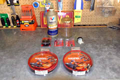
March 2006 The brake system on the CBR 1000RR is pretty adequate in stock form, however I decided to upgrade to Galfer stainless steel lines and make some other modifications at the same time. If you're going to work on the brake system, it's best to do everything at once as anytime you change out a component affected by the brake fluid you have to bleed the brake system. Doing everything at the same time means you only have to bleed the system once which saves time and money on brake fluid. With these upgrades you will gain braking performance, drop 0.59 lbs of weight from the bike, clean up the tail section, and make future brake maintenance much easier to perform. You'll need Galfer stainless steel brake lines, some DOT 4 brake fluid (I like Valvoline Syntec), a 15cc Brembo reservoir, zip ties, some plastic 3/8" (10mm) cable clamps, and some Speed Bleeders. The Speed Bleeders on the 1000RR front calipers are of a different size than those on the front master cylinder and rear caliper, so be aware of that. The front calipers are 7mm x 1.0 and the front master cylinder and rear brake caliper are 8mm x 1.25. You'll also need some kind of container to catch the brake fluid in when you drain the stock lines, as well as when you bleed the system after installing the new components.
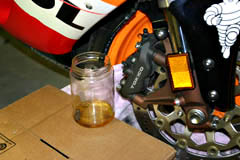
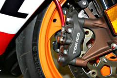
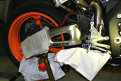
You'll need to begin by removing the 12mm banjo bolt that holds the stock brake lines to the front calipers. Once you've removed the lines from the calipers, set them into your container and let them drain for 10 or 15 minutes to get most of the fluid out of the lines and front master cylinder reservoir. BE CAREFUL with the brake fluid. It can eat painted finishes according to warnings on the container. Keep plenty of rags around and cover any areas of the bike where it's obvious brake fluid could drip on a painted surface.
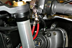
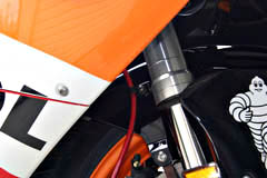
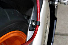
Once the stock front brake lines are drained of fluid, disconnect them from the front fender by removing the 10mm mounting nut. Next remove the 8mm bolt holding the stock front line mounting grommet to the forks behind the front fairing close to the horn. Finally, remove the 12mm banjo bolt that attaches the front lines to the front master cylinder. Again be careful of any brake fluid that may drip onto your upper fairings or painted surfaces. Next, attach the Galfer lines to the front master cylinder and route them down toward the front calipers. The Galfer line meant for the right caliper is shorter than the one for the left. The right line should be first against the master cylinder, then the left line should be on top of the right, then the included Galfer 14mm banjo bolt. Be sure that you have the included crush washers between the connections sandwiching the lines between washers. The order is crush washer, ss line, crush washer, ss line, crush washer, then the banjo bolt using a total of 3 crush washers at the master cylinder. Next attach the right and left Galfer lines to the front calipers using the included Galfer 14mm banjo bolts. Again sandwich the line between crush washers using two crush washers at each caliper. Come back with zip ties and tidy up the lines. Next, mount the Galfer lines to the front fender using the plastic 3/8" cable clamps. You may need to slightly enlarge the mounting hole of the plastic cable clamps in order to re-use the stock front fender mounting location. Once the lines are installed, fully compress, extend, and move the steering from lock to lock to make sure there is absolutely zero binding of the lines. The torque value for the Galfer 14mm banjo bolts is 12-15 ft/lbs (16-20NM). Be careful not to over tighten.
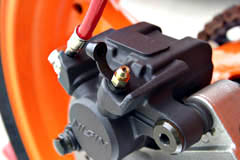
Once the front is complete, move to the rear. Remove the stock 12mm banjo bolt at the caliper and let the stock line drain. Then remove the 12mm banjo bolt that attaches the stock line to the rear master cylinder. Protect the painted surfaces of the bike with rags. Remove the 5mm button head hex bolt that mounts the stock rear line to the swing arm and remove the stock rear line. Install the Galfer ss line using the included 14mm banjo bolts and again be sure to sandwich the lines between crush washers at the caliper and rear master cylinder. Torque the Galfer banjo bolt to 12-15 ft/lbs (16-20NM). Use one of the 3/8" cable clamps to replace the stock grommet that mounts the ss line to the swing arm. Make sure the line is secured in such a way that it will not come in contact with the rear tire.
Installing Speed Bleeders is optional, but they greatly reduce the time required to bleed the brake system. I'd say it's at least twice as fast to bleed the system if not faster. They're cheap and easy to install so there's really no reason not to change them out while you're working with the brake system. Speed Bleeders incorporate a small valve that will only allow fluid to flow one direction meaning you can loosen the bleeder a couple of turns, and simply pump the brake lever until all the air bubbles are removed from the brake system. With standard bleed valves you'd have to loosen the bleed valve, depress the brake lever, tighten the bleed valve, then release the brake lever. You'd have to complete that cycle over and over until all the air was removed from the system. If you make a mistake and forget to tighten the bleeder before releasing the brake lever you'll draw air back into the brake system and have to start all over. As you can see Speed Bleeders are a great asset. To install Speed Bleeders simply remove the stock bleeder valves with a 10mm wrench. Replace the bleed valves at the front calipers with 7mm x 1.0 Speed Bleeders. The torque value for the front caliper bleeders is 5.8 ft/lbs (7.8NM). Replace the front master cylinder bleeder with a 8mm x 1.25 Speed Bleeder and do the same for the rear caliper. The torque value for the front master cylinder and rear caliper bleeders is 4.3 ft/lbs (5.8NM). Be aware of the front caliper bleeders being of smaller size than the front master cylinder and rear caliper. Some parts books even miss this fact, so be sure to ask for verification when ordering. You can tell no difference between a Speed Bleeder and a standard bleeder by appearance.
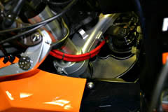
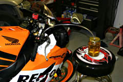
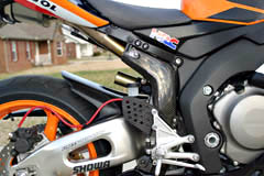
Since I was already working on the brake system, I decided to go ahead and condense my stock rear brake reservoir into a Brembo 15cc unit and mount it closer to the right rear set. This cleans up the tail end of the bike, especially if you remove the passenger foot pegs. You'll begin by removing the 8mm hex bolts that hold the right passenger foot peg in place. Next disconnect the rear brake reservoir hose from the master cylinder and let the reservoir drain into a container. Once it's drained, remove the 10mm bolt that holds the rear brake reservoir to the sub frame.
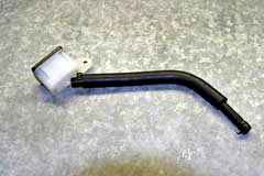
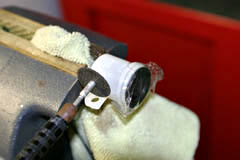
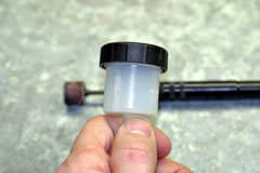
Next, I shaved the plastic tab off the Brembo 15cc reservoir to give it a cleaner look. I just used a dremel tool with a cut off wheel, then used a dremel sanding wheel to even it up. Finally I did a light sanding with 220 grit sand paper to clean up the area. I put a little bit of tape over the reservoir opening to protect it from any debris caused by the cutting and sanding.
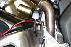
Then you can either cut a piece of the stock rear brake reservoir hose, or use a piece of 1/4" reinforce fuel line to mount the the Brembo reservoir to the rear master cylinder. You can measure to determine what length of line will work best for you, but I found 2.25" - 2.5" (57mm-64mm) worked best for me to allow the reservoir to clear the heel guard. Re-use the stock hose clamps to attach the hose to the Brembo res, then the Brembo res to the rear master cylinder.
With the stock rear brake reservoir removed you can shave the reservoir mounting tab off the sub frame using a dremel cut off wheel. Once it's cut from the sub frame, use the dremel sanding wheel to even up the cut area, and finally use some 150 and 220 grit sand paper to finish it off. Then just hit it with a shot of black spray paint. I used the same BBQ Black grill paint that I used on my sub frame which doesn't require primer. Be sure to cover the rear of the bike with some old towels when shaving this tab off the sub frame as it creates quite a bit of dust.
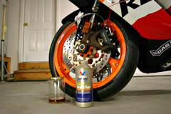
Finally, bleed the brake system. I found 3/16" (4.8mm) clear vinyl tubing to fit the bleeders the best. Just attach the clear tubing to the bleed valve, loosen 2-3 turns and pump the brake lever until you see absolutely NO bubbles left in the clear vinyl tube. When bleeding a brake system you always want to start with the bleeder farthest from the master cylinder, in this case the left caliper on the front, then do the right, then do the front master cylinder. Be sure you have plenty of DOT 4 brake fluid on hand. I used an entire quart.
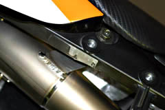
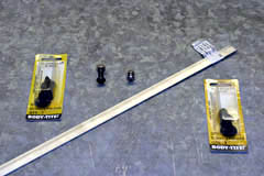
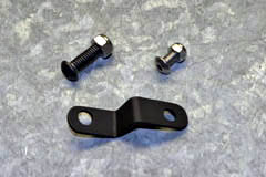
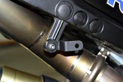
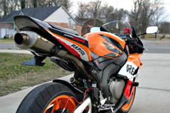
You'll want to thoroughly test the brake system before taking the bike out in traffic. Give the brakes some good hard presses while parked and check for leaks at all the connection points. Make sure the brake levers are firm and not spongy. If they still feel spongy you didn't get all of the air out of the system. Once you've done these two steps, take the bike to a safe controlled location and test the brake system in action. Make sure it reacts the way you would expect. If you want to remove the passenger foot pegs AND keep your exhaust heat shield cover in place you'll need to fabricate a small bracket as the heat shield cover mounts to a bracket that is attached to the right passenger foot peg. This bracket is pretty easy to fabricate and if done properly will look like a stock piece once complete. I used some 1/2" x 1/16" (12.7mm x 1.6mm) aluminum bar stock. Simply cut a 2.25" (57mm) piece and bend it to fit the rear exhaust bracket and drill a hole in each end to match up with the bracket and the heat shield cover. I then used a black 30mm long 5mm button head hex bolt to attach the fabbed bracket to the bike. I also used a stainless nut with nylon lock washer to secure it. Finally just use the stock 5mm button head hex bolt along with another stainless steel nut with nylon lock washer to secure the heat shield cover to the other end of the fabbed bracket. I've got an aftermarket carbon fiber heat shield in place of the stock aluminum heat shield and cover, but this should work for the stock one as well. I also used some GM 45490 body plugs to fill the holes in the sub frame where the passenger foot peg bolts went. These plugs are available at just about any auto parts store. This finished the bike off and made it look totally stock.
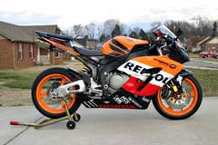
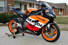
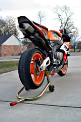
I'm very happy with these upgrades. They are a little time consuming so set aside an afternoon to complete everything. You'll want to take your time and be sure to do things in the proper order and be very thorough. The bike looks much better with the rear reservoir modified and the passenger foot pegs removed. The brakes have a much firmer feel and the red Galfer lines I used accent the bike nicely with the Repsol color scheme.
This page is part of a frame set. If you reached this page via a search engine please click here to go to the main page. |