 |
 |
Honda CBR 1000RR Clear Alternatives Integrated Tail Light Install
February 2005
I don't particularly care for the stock
turn signals that come on these sport bikes. They don't seem to have been
updated, on most models, since the early 1990s. I also don't care to run
around without turn signals as I see so many sport bike riders do. To me
this is both dangerous and irresponsible for riding on public roads. One solution is to purchase a
tail light unit that integrates the turn signals into the tail light. This
will give you the best of both worlds, having the sleek performance look while
maintaining safety.
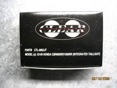
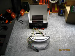
LED technology has allowed manufacturers to incorporate different colored LEDs in different parts of lighting schemes. In terms of an integrated tail light, there are three levels of lighting. One is the tail light itself, a large set of red LEDs. Second is the brake light, again red LEDs only very bright ones. Third are sections of orange LEDs that illuminate when the turn signals are activated. There are a few manufacturers that offer integrated tail lights. After doing quite a bit of research, Clear Alternatives' design was determined to be the easiest to install, most complete unit, and the most cost effective compared to some other offerings. The Clear Alternatives P/N for the CBR 1000RR is CTL-0062-IT. The Clear Alternatives unit comes complete with the tail light, wiring harness, and power sinks.
|
|
|
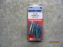
Installing such a unit on a Honda CBR 1000RR is a pretty simple task, although a little time consuming if you want it done right. My advice is not to wait until the day before a big ride or bike night, and decide to attempt the install. You definitely don't want to rush the job. You'll need some heat shrink tubing, weather proof heat shrink butt connectors, some twist connectors, and plenty of electrical tape. You could take short cuts and just use splice connectors, but this is not recommended.
 |
 |
 |
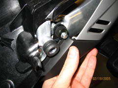
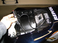
Begin by removing the passenger seat along with the rider seat. There are two 5mm pan head hex bolts underneath the back of the rider seat holding it in place.
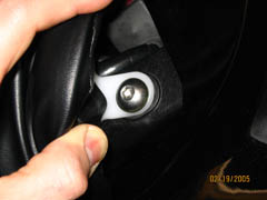
The rear cowl is held in place by four 5mm pan head hex bolts. Keep track of which hex bolts go where as they are not identical. Two are under the passenger seat, and two are on the sides of the cowl close to the rider seat. Unplug the stock tail light and the rear cowl will come free of the bike. You have to bend the rear cowl out a bit to get it to clear the tail sub frame.
 |
 |
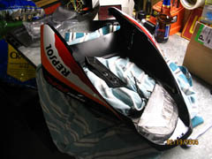
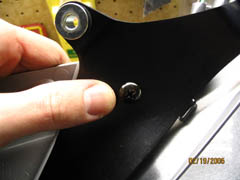
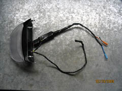
Remove the stock tail light from the rear cowl by removing the 2 philips screws holding the two mounting brackets in place. Note that the brackets are marked R and L for right and left. Remove the stock tail light from the light bracket by removing the two 8mm nuts. Be sure to put something underneath the rear cowl while working on it to avoid scratches.
|
|
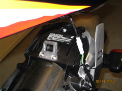
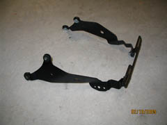
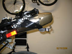
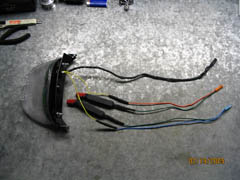
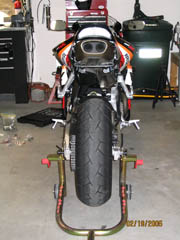
The stock turn signals are held on the bike by an intricate bracket assembly that is connected to the rear fender. Remove the four 8mm bolts holding the rear fender in place. Unplug the turn signal and license plate light connections on the left rear side of the bike. Remove the rear fender. Remove the left side silver fin on the rear fender by removing the philips head screw. This will allow you to remove the turn signal and license plate wiring. Remove the stock turn signals by removing the two 10mm bolts holding them in place. Here you'll have to decide if you're going to re-install the rear fender, fabricate some other type of license plate bracket, or buy an aftermarket license plate bracket.
 |
 |
 |
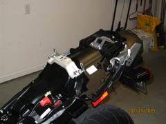
For the time being I elected to fabricate a fender eliminator from stock parts. I'll use this until I find one I like or design and build my own. I basically used the sides from the original fender and a left over license plate bracket from a previous bike. I flipped the license plate bracket upside down to bring it closer to the exhaust.
 |
 |
 |
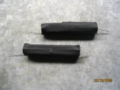
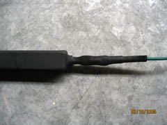
Now that the bike is prepped for the new rear tail light, we need to work out the wiring for the integrated tail light. The Clear Alternatives tail light is a direct bolt on replacement for the factory tail light. The wiring for the tail and brake lights just plugs right into the stock wiring harness. The turn signals are a little more tricky. When you hook up the LED turn signals they will flash twice as fast as the stock bulbs. This is due to the LEDs drawing less power than the stock system. Correcting this is optional, however I chose to do so as the fast flashing of the turn signals was a little too fast for my tastes. Clear Alternatives includes some power sinks that can be wired in parallel to the LED turn signal wiring that will bring the turn signal blink rate back to stock speed. Be sure to use water proof heat shrink connectors for all electrical connections. I even recommend adding heat shrink tubing on top of the water proof connections for good measure. I began by putting heat shrink tubing around the power sinks to protect them.
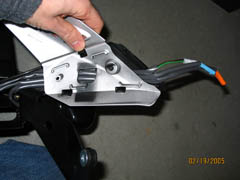
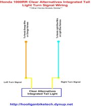
EASY WIRING METHOD:
The
YELLOW wires coming out of
the Clear Alternatives tail light are the turn signal power wires. These
should be ran to the +12V wires for the stock turn signals on the bike. On the
1000RR,
the LIGHT BLUE wire is the LEFT turn signal
+12V and the
ORANGE wire
is the RIGHT turn signal +12V.
GREEN on the 1000RR is ground. Note that Honda color coded the
actual plug in connectors ORANGE and LIGHT BLUE as well. If you're not concerned about the
fast flash condition, just hook up the YELLOW wires to the corresponding LIGHT
BLUE or ORANGE wire on the stock turn signal wiring on the bike and you're done.
Be sure to test for proper RIGHT and LEFT turn signal operation prior to making
any final connections.
The only complaint I have on the Clear Alternatives tail light is that they didn't color code the right and left turn signal wires as they are both YELLOW. You'll have to hook one of them up temporarily and turn on the turn signal to see which side is flashing and adjust as necessary. The tail light connection uses a common ground so you only need the YELLOW connection if you don't mind the turn signals flashing fast.
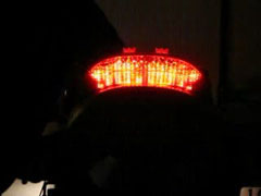
FAST FLASH CORRECTION WIRING METHOD:
If you're like me and want the turn
signals to flash at the correct frequency, you'll have to wire the power sinks in parallel
with the turn signal wiring. The power sinks act as a load on the wiring,
fooling the turn signal relay into thinking there is a bulb installed, rather
than the low wattage LEDs. I prefer my wiring to be as clean and as
non-intrusive to the bike as possible, so I cut the connectors off the stock
turn signals and spliced them into the Clear Alternatives wiring so that I had a
direct plug in unit. You could make up your own wiring and splice into the
bikes wiring but I personally don't like to affect the bike's wiring at all.
Be sure to test for proper RIGHT and LEFT turn signal operation prior to making
any final connections as both the LEFT and RIGHT turn signal wires are YELLOW
coming from the Clear Alternatives wiring harness. The difference in the
correct flashing frequency and the fast flash condition is shown in the video
below.
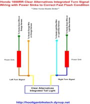
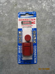
To make this parallel connection, you'll need to use the twist connectors shown above. Connect the YELLOW wire that controls the LEFT turn signal coming from the Clear Alternatives harness to one end of the power sink and twist them together along with the LIGHT BLUE wire from the stock turn signal connector. Secure the three twisted wires together with one of the twist connectors. Do the same for the other YELLOW wire, power sink, and ORANGE wire. Connect the other end of each power sink to the corresponding GREEN wire on each respective LEFT and RIGHT turn signal wire from the connector cut from the stock turn signals. Be sure to wire the power sinks about 12 or 14 inches from the tail light. This will place them in a prime location to be hidden inside the rear cowl once the project is complete. Again, I recommend using heat shrink water proof butt connectors, and covering them with heat shrink tubing. Following this method should give years of trouble free operation.
 |
 |
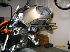
Once the wiring is all connected and in place, wrap everything with a high quality electrical tape. Reinstall the tail light in the reverse of removal. Be sure to remember the silver mounting brackets that hold the tail light to the rear cowl are marked for right and left. Reinstall the rear cowl and plug in the connections to the bikes connections. The wiring for the tail light including the power sinks should easily be hidden on the left side of the rear cowl behind the vent.
 |
 |
 |
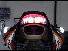
This provides a much cleaner look and I really dig the integrated turn signals. The total project time with simple wiring is about 1 hour. Double the install time to around 2 hours for the more complex method.
This page is part of a frame set. If you reached this page via a search engine please click here to go to the main page.