Performance Gauges
Part of preparing for the TRD Supercharger was deciding on what vehicle metrics to monitor. After a lot of reading online forums to see what other people were doing, I decided to put in an AFR (air fuel ratio), boost, and tranny temp gauge since I have the auto tranny. Some other metrics to consider are exhaust gas temperature and fuel pressure, however my thinking is that if AFRs are in line, then these two metrics will be as well.
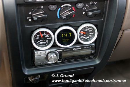
The AFR gauge is by far the most important as it tells you what the engine is doing from an air to fuel perspective. In my initial research I learned the TRD Supercharger had a tendency to cause the engine to run lean and with an AFR gauge I can see what is going on from a combustion stand point and take the necessary corrective action. Modern ECM controlled car engines will try to run at stoich which is an AFR of 14.7 pounds of air to 1 pound of fuel. This is too lean in a supercharged application which should be in the 11.5 - 12.0 range while in boost and depending on the application. A heavier vehicle like a 4Runner should be set at 11.5 - 11.8 while a lighter vehicle could be set to 12.0. I chose Innovate's LC-1 Wide Band with DB gauge for my AFR gauge solution. Innovate only offers the DB gauge in blue or red LEDs so I called Nordskog, the company that makes the DB gauge for Innovate, and asked them to custom make me one with green LEDs.
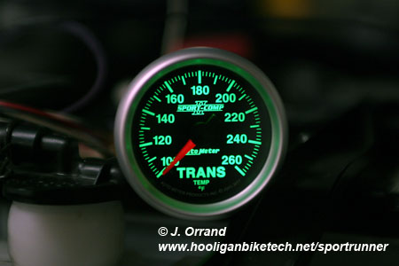
The second most important gauge is the tranny temp. The Supercharger has shown to place stress on the auto tranny due to it's luxury (read soft) shifts and monitoring the temperature can help avoid problems and show if preventative measures should be taken such as an additional tranny cooler or valve body upgrade.
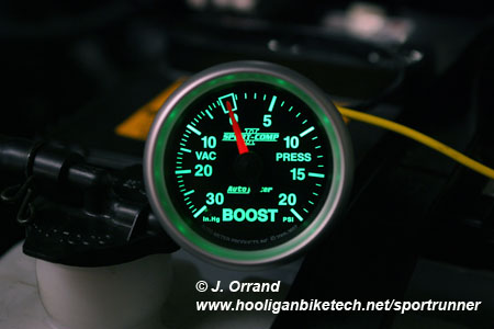
I had room for three gauges and chose a boost gauge as the third. In the future I do have the option to move the boost gauge to the driver's side A pillar and put in a more critical gauge such as an EGT (exhaust gas temperature) gauge, or fuel pressure gauge, should I deem one of those necessary.
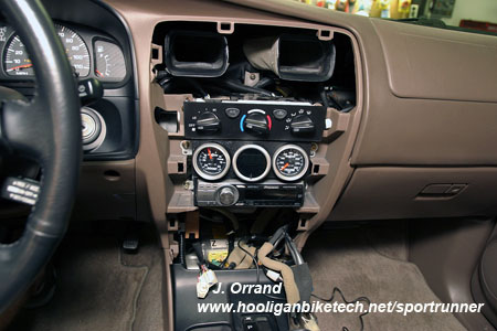
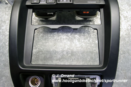
This part of the project was highly involved as I wanted the gauges somewhat hidden from outside view and appear as if they came in the vehicle from the factory. I had already replaced the factory double DIN stereo with a single DIN unit so mounting the three gauges above the head unit seemed like a logical choice. The problem was they needed to angle toward the driver in order to provide a better view and due to limited space I had to fabricate my own angle rings which added to the project's complexity.
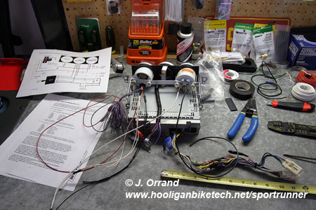
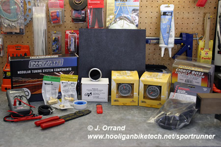
For this project you'll need:
Your choice of gauges - there are many
varieties available but I really like
Auto Meter's offerings
Dash panel available from stereo shops
3 - 4 rolls of 16 gauge wire in various colors - I tried to match my colors to
those on the gauges so I chose white, red, blue, and black
Plenty of high grade electrical tape
20 feet of 3/8" corrugated
wire
loom
20 feet of 3/8" HIGH TEMP corrugated
wire
loom - denoted with a gray stripe down the loom
20 feet of 1/4" corrugated
wire
loom
20 feet of 1/4" HIGH TEMP corrugated
wire
loom - denoted with a gray stripe down the loom
2 packages 3/16" heat shrink tubing - I prefer the GB Electric brand
3 packages 1/4" heat shrink tubing - I prefer the GB Electric brand
1 package 1/2" heat shrink tubing - I prefer the GB Electric brand
1 package of 18 - 22 gauge male and female insulated spade connectors - I prefer
GB Electric brand
3 packages of 14 - 16 gauges male and female insulate spade connectors - I
prefer GB Electric brand
1 package of "T" taps
1 package of 12 gauge ring terminals
1 package of 14 - 16 gauge ring terminals
1 package of 14 - 16 gauge butt connectors
Plenty of zip ties in small, medium, and large sizes
A GOOD wire stripper tool
A GOOD wire crimping tool
Test light or digital volt meter
Dremel tool with sanding wheels and cutting tool
Drill and assorted drill bits
Saw with plastic and metal cutting blades - I used a compound miter saw
Hack saw
1/2" aluminum bar stock
Metal pipe for the angle rings
Brass "T" with 3/8" barb
Two 3/4" stainless hose clamps
Teflon sealing tape
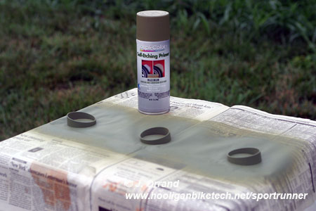
Etching primer
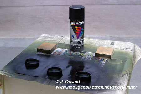
Spray paint
Various small nuts, lock washers, and bolts in the 8 to 10 size range
Tape measure
Automotive double sided tape
A small bag of assorted rubber grommets
Green LED - optional
Micro SPST switch - optional
Soldering gun and solder
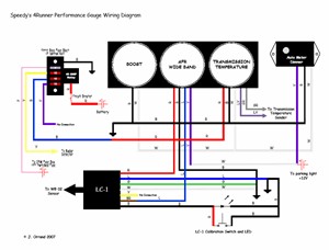
*NOTE: This is a large wiring project so make sure to have plenty supplies related to wiring on hand to avoid multiple trips to the hardware store. Some of these items such as the wire loom and heat shrink tubing are optional, but necessary if you want a bullet proof and factory look installation. I highly recommend you create a wiring diagram for your vehicle's gauge installation to follow, as well as to keep in the glove box for future reference such as this one:
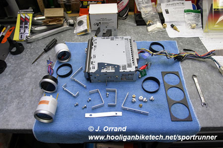
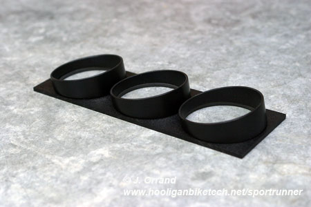
I worked on these gauges over a couple of weekends. It took a lot of patience and is not something you want to rush. Be sure to study all wiring diagrams associated with the gauges you choose as well as the vehicle wiring diagrams from the field service manual. I began by building the bezel and trim rings for the gauges. The bezel was made from a 12" x 12" piece of dash material I picked up from a local stereo shop. The bezels were thin wall metal pipe I found that would just fit the gauge bezels. I chose an angle of 10 degrees for the angle rings and after cutting, sanding, and shaping them I primed them with etching primer and painted them semi gloss black.
|
|
|
While working on the bezel and trim rings, I mailed my Auto Meter Sport Comp II gauges back to Auto Meter to have the white LEDs changed to green to match the vehicle's interior lighting. As mentioned earlier, I also had Nordskog custom make me a DB gauge to go with the LC-1 using green LEDs and Innovate only offered red or blue.
|
|
|
I used one of of the circuits from my Cirkit Boss to provide ignition switched power to the gauges. I soldered the power line from the Innovate LC-1, Innovate DB gauge, and tranny temp gauge together and connected them to one lead from the Cirkit Boss using a 10 amp fuse. The boost gauge is mechanical and does not require switched +12V power to operate.
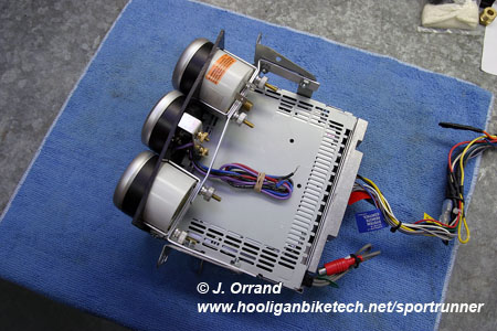
With the bezel, angle rings, and power figured out I tackled building the bracketry to mount the gauges using the 1/2" aluminum stock. Take a lot of measurements and try to piece things together so they are solid and modular so that you can remove gauges for maintenance in the event that's ever necessary. Also be sure to leave room for your wiring.
|
|
|
|
|
|
|
|
|
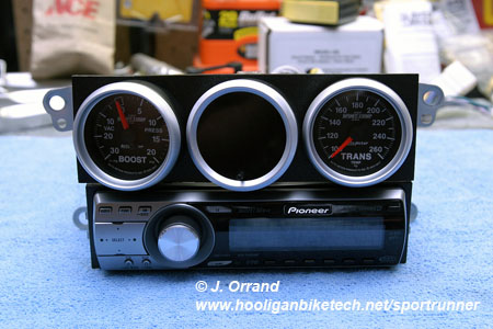
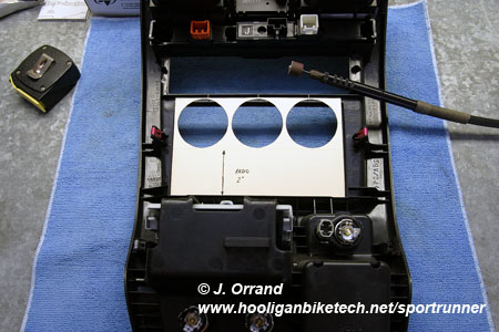
To give a factory installed appearance, I didn't want to just cut the dash trim to make the gauges fit so I used a piece of thick paper and made a template. I then used the template to mark where on the dash the gauges would be so that I could use a Dremel tool to arch the dash trim around the gauges. This provided for a MUCH cleaner appearance. Measure THREE times here and trim on the short side to give plenty of room for error. Once I had enough material trimmed away to allow the dash panel to fit over the gauges, I then used a pencil to mark where to continue trimming so that the arches just barely fit around the gauges. I actually used a micrometer to make sure the trimming was perfect to the closest .001" but that's probably more obsessive than most will choose to be. I'd think you could get very close with a good tape measure.
|
|
|
|
|
|
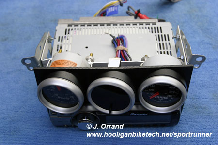
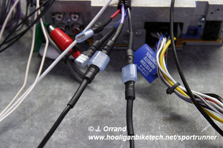
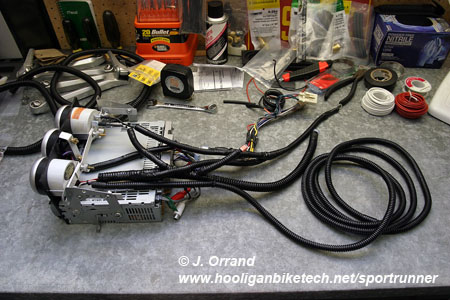
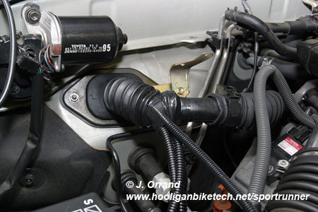
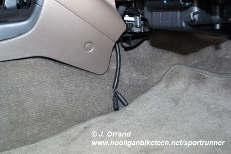
With fitment worked out I began on the wiring, which was the most tedious part of the project. I built a custom harness to plug into the gauges that left enough room for me to remove the head unit assembly when needed. Every connection is heat shrinked and all wiring is covered with the proper loom. Any wires that ran into the engine bay were covered with special high temp loom good to 300 degrees F. This high temp loom is denoted by a gray stripe down the side of the loom. I routed the wires for the LC-1, boost, and tranny gauge out through the large factory boot on the passenger side fire wall area. To get to this area from the interior of the vehicle you'll need to remove the glove box and top tray which is very simple. The hardest part about this process was fishing the wires through the factory rubber boot.
|
|
|
|
|
|
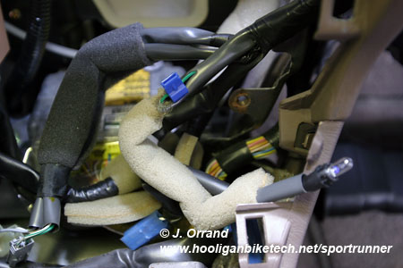
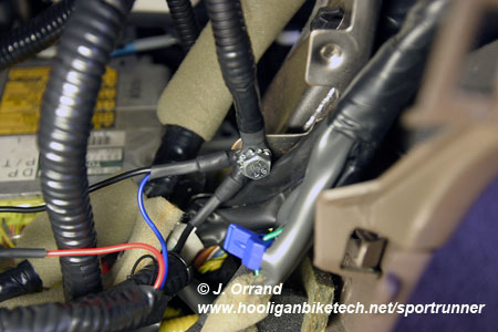
I tapped gauge illumination power from the ash tray lamp's +12V line, which is the green wire in my 2002 4Runner, but check your particular application's field service manual. I used a "T" tap on this line to draw +12V when the parking lights are activated. I grounded everything to the dash frame using a bolt I had in my spare bolt jar and lock washer. The LC-1 manual said to ground it to the engine block, however I found that pretty difficult on my 4Runner so after talking to Innovate support they said the dash frame ground point was fine. I did follow all other LC-1 grounding instructions such as running the LC-1 blue wire separately but grounding to the same location as the white and green wires.
|
|
|
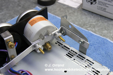
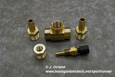
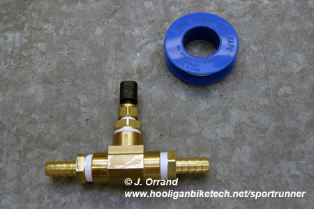
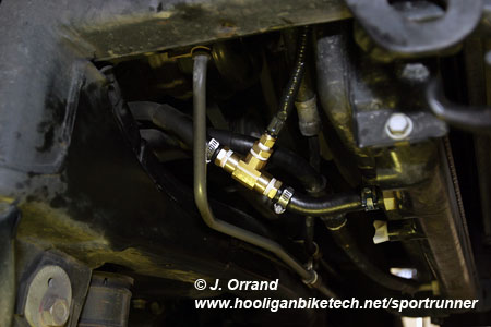
I then put together a 3/8" brass barb "T" using teflon sealing tape for the transmission sender. With the Auto Meter full sweep electric gauges you don't need to ground the sender as it shares it's ground with the gauge ground. This allowed me to install the sender into the soft rubber line coming from the transmission to the stock transmission cooler.
|
|
|
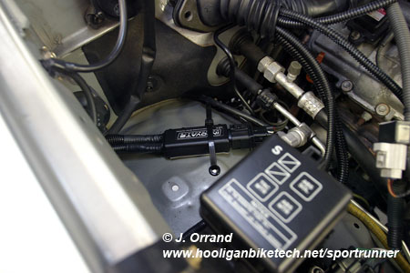
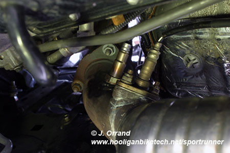
I then found a good spot for the LC-1, which for me was on the passenger side wheel well. I put a couple of rubber O-rings through some factory holes in the fender and used a large zip tie and some double sided tape to secure the LC-1. I ran the sensor cable down the firewall to the bung. Since the sensor cable was within 1 - 2 inches of the exhaust down pipe I wrapped it in some Thermo-Tec adhesive backed heat barrier for added protection as it is good to 2000 degrees F. When having the bung put in for the wide band sensor, make sure it's at the 10 - 2 o'clock position NOT at the 6 o'clock position as moisture in the exhaust pipe can damage the sensor. Also it needs to be before the catalytic converters. The LC-1 serial cables are tucked away in the factory console, but easy to reach when needed.
|
|
|
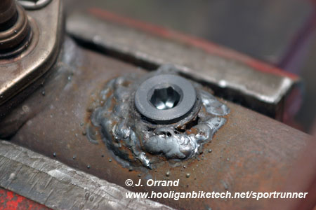
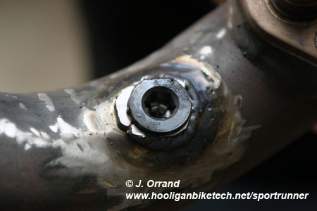
Also, BE SURE you have a good exhaust shop weld the wide band bung. I had a local shop that I thought was good do it for me and they totally blew it. The weld looked like bird poop and leaked. These guys welded the bung on with the cat pipe attached to the truck. I'd suggest the pipe be removed for the bung installation. I ended up taking it to another shop to fix the work. They removed the down pipe and ground off the weld and re-did the work correctly.
|
|
|
|
Nasty weld |
Correct leak free weld |
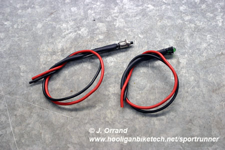
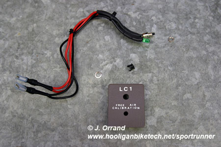
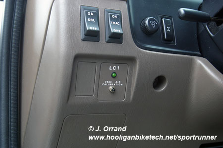
I didn't care for the free air calibration button or red LED that came with the LC-1 so I made my own using a green LED and micro switch. This makes for a much less obtrusive installation. I also labeled the LED and button using the same method of sanding, applying dry transfer letters, and clear coating with semi gloss lacquer that I used on the DRL and VSC/Trac switches. Remember to leave enough wire slack to remove for maintenance.
|
|
|
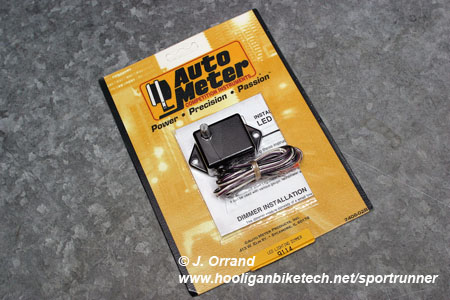
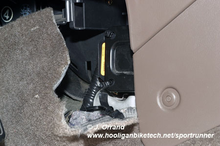
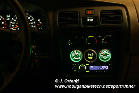
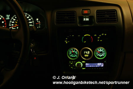
Finally I installed an Auto Meter dimmer for LED gauges, P/N 9114, to tone down the illumination of the Sport Comp II gauges. The Innovate DB gauge automatically dims it's LED display when one of the wires gets +12V so I connected it to the +12V of the ash tray lamp along with the Auto Meter dimmer. The dimmer is a simple three wire hookup and in my opinion necessary as the gauges are BRIGHT and distracting without it. Using LED gauges you can not tap into the factory dimmer as it takes special circuitry to dim LEDs. I mounted the dimmer to driver's side of the lower dash using zip ties. It's hidden but still easy to reach. Below is as shot showing them at full bright and dimmed to match the factory illumination level.
|
|
|
|
|
|
|
Full Bright |
Dimmed to match factory illumination level |
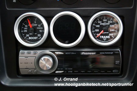
Angling the gauges toward the driver worked out well as shown in the below shot from the driver's perspective.
This gauge project was a ton of work, but in the end it was well worth it. The gauges have a factory installed appearance which is exactly what I was looking for. Total time on this portion of the project is probably in the 30 hour range all said and done, so if you decide to get this detailed spread it out over a couple of weekends to keep from getting tired of working on it.